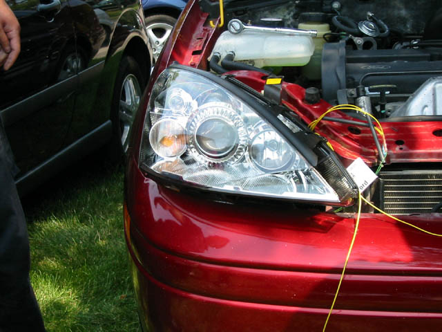
Plug the Ford adaptor into the existing Ford harness. Run the city and turn signal indicator light wires behind the frame and in front of the radiator. Let them dangle over the bumper for connecting to the turn signals (see image below). Connect the VW harness to the back of the new light. It clicks into place.
Test the lights (low and high beams). The high and low beams should stay on if the multifunction switch is held. When it is released at this point the the low beams will turn off, and the high will remain on.
Install the lights by adding 3 bolts back in (the bolt located at the lower inside is no longer needed)
Carefully begin to remove the electrical tape and corrugated electrical tubing on the turn signal lamp wiring harness using the utility knife. Be very careful not to cut the wires unless you never want to use the original turn signals again. Remove the bulb socket from the harness (simple clip-on attachment here). You should be left with a connector that has three (3) openings. The black wire is ground. The other two coloured wires are "MAJOR" (gives you that bright signal light) and "MINOR" (gives you the dim signal light). Having these two alternate gives you your blinking. The problem is that there isn't a set wiring colour used for "Major" and "Minor".
Snap off one of the metal ends of the VW wires that are meant for the city lights and turn signals. Strip off 1/4-inch of the wire and insert it into one of the openings leading to a coloured wire on the existing Ford turn signal harness. Turn your hazard lights and headlights on. Determine which VW wire powers the turn signal, and which wire powers the city lights. Make note of which wire does what using the masking tape and marker.
Splice into the existing turn signal harness wires by carefully using a wire stripper to cut through the outer wire about one inch down the wires. Be very careful not to cut the wires unless you never want to use the original turn signals again. Cut the wires from your custom harness to length and add an extra inch or so just in case. Solder the appropriate lead to the wire with the wire leading up towards the adapter as shown below. Cover the exposed wires with electrical tape as there is not much room for shrink coverings.

After both wires are spliced, put the wires into the original guard and wrap the end with electrical tape.

Take the wiring harness and slip it under the lip between the top and bottom just under the frame where the wire comes out. Feel around for it and you'll know what I'm talking about. It feels like it was designed to hold these wires in place.